続いて本体のソフトウェアに移ります。前回出てきたArduino UNO Rev3というマイコンで動かすのですが、プログラムを入れてやらないと動きません。今回はそのプログラム編です。
まずはArduinoIDEというソフトをインストールします。この辺はgoogle先生に「Arduino 始め方」あたりで聞けば教えてくれますので、各人調べて下さい。
ArduinoIDEを起動したら、スケッチ→ライブラリをインクルード→ライブラリマネージャを起動します。起動したら検索窓に「sakuraIO」と入れるとさくらIOのライブラリがでますので、インストールします。もしかしたらTimerOneライブラリもいるかもしれません(私はすでに色々入れているので、、1からだとどれが要るのかいまいち分かりません)。さて、メイン画面に
ーーーーーーーーーーー
void setup() {
// put your setup code here, to run once:
}
void loop() {
// put your main code here, to run repeatedly:
}
ーーーーーーーーーーーー
多分こんな画面が出るので「全部消して」、以下のものをコピペしてください。ーーーーーーの部分は要りません。
ーーーーーーーーーーーー
#include <Time.h>
#include <TimeLib.h>
#include <SakuraIO.h>
#include <TimerOne.h>
SakuraIO_I2C sakuraio;
//50Hz地区では、SMP_NUMを67→80、WAIT_NUMを3933→3920へ変更する
#define SMP_NUM 67
#define WAIT_NUM 3933
uint32_t unixtime;
float Irms = 0;
float Watt = 0;
float total_Watt = 0;
float total_Irms = 0;
float Watt_hour = 0;
int smp_status = 0;
int cal_status = 0;
int sec_cnt = 0;
int A[SMP_NUM];
int arrNUM= 0;
void timercall() {
int a,r;
if (smp_status == 0) {
a = analogRead(0);
A[arrNUM] = a – 511;
arrNUM ++;
if (arrNUM == SMP_NUM) {
arrNUM = 0;
smp_status = 1;
cal_status = 1;
}
}
else {
arrNUM ++;
if (arrNUM == WAIT_NUM) {
arrNUM = 0;
smp_status = 0;
}
}
}
void wattcal() {
float amp;
Irms = 0;
Watt = 0;
for (int b = 0; b < SMP_NUM; b++) {
amp = A[b] * 5.0 / 1024 * 200;
Irms += amp * amp;
}
Irms = sqrt(Irms / SMP_NUM);
Watt = Irms * 105;
}
void outputcal() {
total_Watt += Watt;
total_Irms += Irms;
Watt_hour += (Watt / 3600);
sec_cnt ++;
if (sec_cnt == 300) {
sec_cnt = 0;
if ((hour() > 4) && (hour() < 20)) {
sakuraio.enqueueTx(1, (abs(total_Watt) / 300));
sakuraio.enqueueTx(11, abs(Watt_hour));
sakuraio.enqueueTx(21, total_Irms / 300);
sakuraio.send();
}
total_Watt = 0;
total_Irms = 0;
if (minute() < 15) {
unixtime = (uint32_t)(sakuraio.getUnixtime() / 1000UL);
if (unixtime != 0){
setTime(unixtime + (9 * 60 * 60));
}
}
if ((hour() == 3) && (minute() < 15)){
Watt_hour = 0;
}
}
}
void setup() {
Serial.begin(9600);
pinMode(15,OUTPUT);
pinMode(16,OUTPUT);
digitalWrite(15,HIGH);
digitalWrite(16,LOW);
for (;;) {
if ( (sakuraio.getConnectionStatus() & 0x80) == 0x80 ) break;
delay(1000);
}
for (;;) {
unixtime = (uint32_t)(sakuraio.getUnixtime() / 1000UL);
if ( unixtime != 0 ) break;
delay(1000);
}
Timer1.initialize(250);
Timer1.pwm(9, 512);
Timer1.attachInterrupt(timercall);
}
void loop() {
if (cal_status == 0) {
delay(1);
}
else {
wattcal();
outputcal();
cal_status = 0;
}
}
ーーーーーーーーーーーーーーーーーー
東日本(50Hz地域)の方は、書いてある通りプログラムを修正してください。西日本(60Hz地域)の方はそのままでOKです。
その後、ArduinoとパソコンをつないでArduinoに書き込んでください。その辺のやり方は先ほど「Arduino 始め方」で調べたページに書いてあると思います。
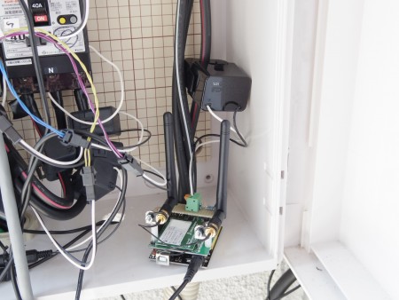
書き込みが終わったら、本体を設置します。
※単相であることを前提に話を進めます
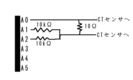
主幹ブレーカーから赤、白、黒の線が出ていますが、赤か黒のどちらかにCTセンサを噛ませてください。CTセンサの向きはどちらでも良いです。その後ACアダプタから本体に給電します。
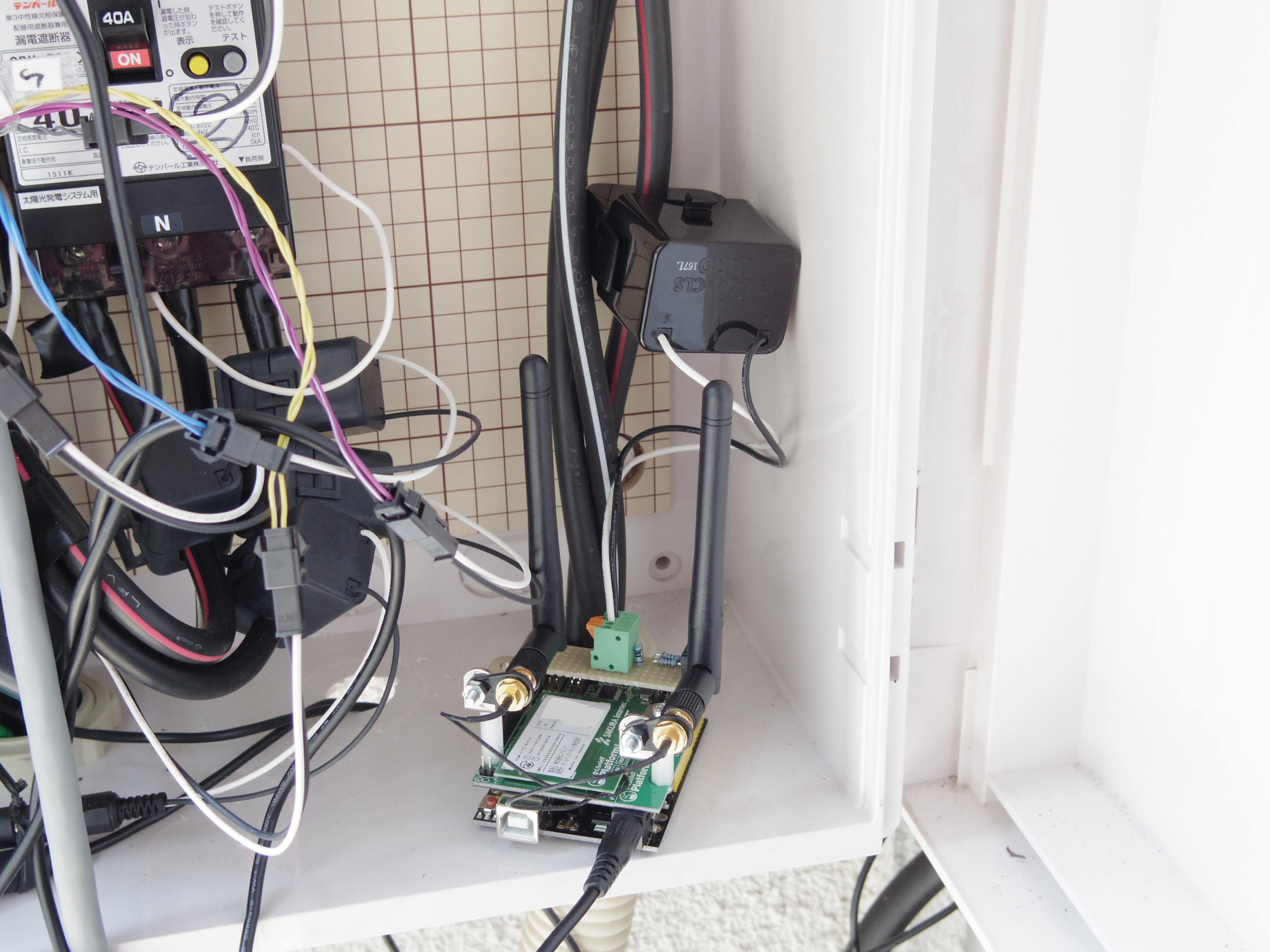
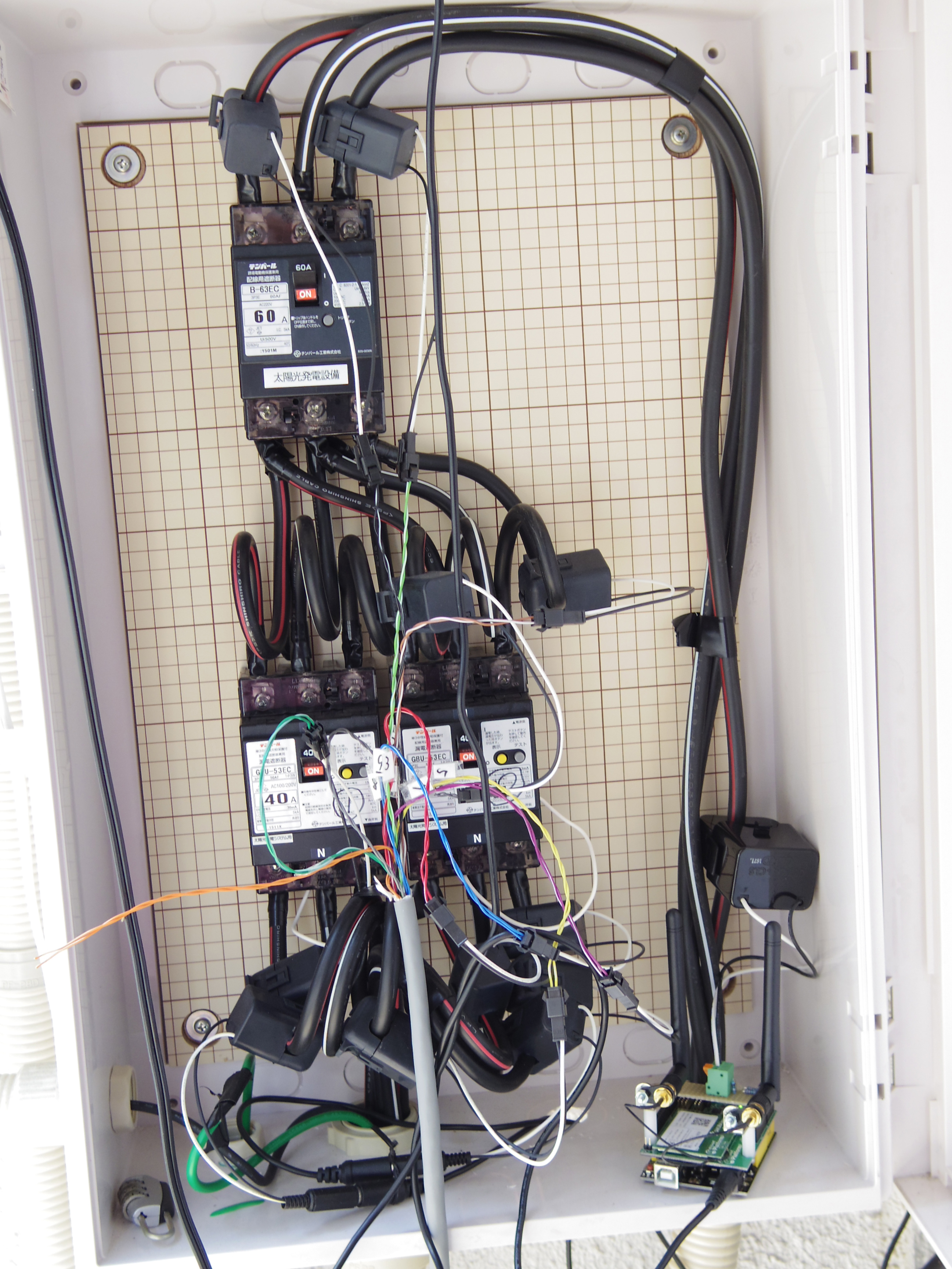
※CTセンサには向きがあるのですが、今回作るものは向きを気にしなくて構いません。
※3相につける場合は、3本の線(R,S,T)のどれにつけても構いません。
※写真の配電盤はCTセンサだらけですが気にしないでください。ウチのテスト環境です。
第2回はこれで終わりです。お疲れさまでした。


コメントを残す
コメントを投稿するにはログインしてください。